The inevitable Nixie tube clock
On eBay I bought a cool HP 5245L frequency counter from the late 1960s with an 8-digit Nixie tube display, paying little more than a shipping charge. It's an amazing piece of technology. It uses a so-called ovenized timebase--a crystal oscillator in a thermostatically-controlled heated enclosure for temperature (and thus frequency) stability. When new it promised stability of 2 parts in 1010; it's now old enough that at an aging rate of 3 parts in 109 per day it has almost certainly slowed down over the intervening ~109 seconds. (This is because crystals relax over time and change their oscillating frequency.)

Electronically the unit is remarkable because it uses no integrated circuits--it is constructed entirely from discrete components. It's worth pointing out that this is essentially what was used on the Apollo program to land on the moon, though the navigational computers for the CM and LEM were built with simple RTL integrated circuits, just a small step beyond this technology.
The counter is built mostly on plug-in boards populated with hefty transistors. The logic levels are +20V (1) and -10V (0), and the circuits draw some significant current.


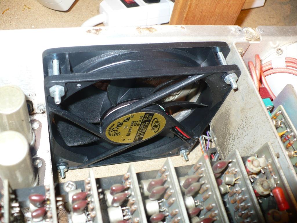
This means they also produce some significant heat, which is why the unit had a very large (and loud) cooling fan. My aim in using the counter for a project was to stick entirely to technology of its time--no ICs, microprocessors, or the like--but I made one exception, replacing the noisy 110V fan with a modern 12V one that is nearly inaudible. Luckily the dimensions were identical and the mounting holes lined up exactly. I am pretty sure it moves enough air . . .

The frequency counter works by gating the input signal for a precisely-measured time derived from its crystal timebase. The unit simply counts the number of cycles during the gate time and displays it. The trick is that the timebase generates pulses exactly a second long so there is no math involved. For faster signals (up to 50 MHz) it simply gates for fractions of a second (10ths, 100ths, 1000ths, etc.) and moves the display's decimal point--everything is a power of 10. (The plug-in unit on the right of the top picture actually extends the range to several GHz by using a resonant chamber to divide a high-frequency signal down to the range of the counter.)
The heart of the unit is a series of cascaded circuits, one for each digit, that both count from 0 to 9 and drive a Nixie tube for display. These are the most interesting parts of the counter. Each pair of cross-coupled transistors (the larger circles in the schematic) is a bistable multivibrator--a flip-flop, essentially--that alternates from one state to another when nudged. One state represents binary "0" and the other binary "1."

Four of these are sufficient to represent the decimal numbers 0 to 9. If you do the math you will find that four bits (8-4-2-1) can actually represent 0 to 15, but these are wired as decade counters--they roll over from 9 to 0 with a pulse to "carry the one" to the next most significant digit when they go from 9 to 0. They do this by carrying pulses both forward and back during the count, effectively making the bits represent 1-2-4-2 (adding up to 10).

(The diagrams here are from the fabulously detailed manual, which includes the complete theory of operation and full schematics.)
These circuits also drive the Nixie tube display, an interesting problem with this technology (and newer ones, too). A Nixie tube is essentially a neon bulb with 10 filaments, one in the shape of each decimal digit. It runs on about 150V, which is too high to handle with small switching transistors. So the HP designers found a way to isolate the high voltage from the (lower) logic voltages. The row of small circles represents little neon bulbs, one each for "0" and "1" in each bit. They illuminate an array of photocells (the circles near the top of the schematic) in combinations of 3; the cells are arranged so that a given combination of three corresponds to exactly one filament (digit). (The little black squares on the schematic show, as an example, which lamps are lighted to produce zero on the display--four "0" bits illuminating three series-connected photocells that ignite the zero in the Nixie tube.) This is a 1960s optoisolator, and very cool.
So what to do with this device given that I already have a Nixie-tube frequency counter? It's a cliché but I decided to make a clock. Yes, everyone does this. As I mentioned, though, I decided to do it using only 1960s technology, and indeed most of the components were harvested from junked electronics of the era. Another aim was to use as much of the counter's existing circuitry as possible.
Obviously the timebase, producing 1 pulse per second (or decimal multiples), was to be the basis of the clock. The unit provides the output of its highly-accurate crystal oscillator at the back of the unit, with a switch to choose the frequency in multiples of 10, and I simply fed this signal to the input of the counter. There are other ways, but this method has the advantage of allowing the clock to run not just at normal speed but also 10 or 100 or 1000 times faster. This is great for testing and provides a very simple way to set the clock: Speed through the hours, gradually slowing down as you approach the current time, just like a modern digital clock but requiring no additional circuitry.
So the clock just needs to count 1-second pulses to keep time, but do you make a decimal counter into an hours-minutes-seconds clock? This has been done many times (as a Web search will show) and the theory is easy to figure out. A clock is just a counter whose two "seconds" digits roll over from 59 to 0, whose two "minutes" digits do the same, and whose "hours" digits roll over from 12 to 1 (for a 12-hour clock). The first two are implemented the same way, detecting "6" in the tens digit and generating a carry (and reset to 0) on that instead of on nine-to-zero. A look at the state table above shows that the most significant bit ("D") changes from 0 to 1 on exactly that transition. So I tapped the transistor corresponding to that bit (actually the inverse, "not D," so that I had a negative-going pulse needed for the reset/carry) and fed it into the reset line of the appropriate digit. You can see the wires in the overview above.
The circuit actually is actually very sensitive, and simply feeding the logic level back turned out to freeze the counter. So the carry/reset is buffered by an emitter follower.

The hours rollover is a little more complicated because it requires detecting "13" in the two hours digits. Three bits turn out to be sufficient: "1" in the tens of hours (least significant bit) and "3" in the hours (the two least significant bits). When all are "true" (logic level "1") we are at 13. This is a simple AND that can be realized with diode-transistor logic. (I adapted a circuit from K6JCA.) This generates a reset/carry pulse. I rewired the reset for the hours digit (reset line goes to the "true" side of the least significant bit rather than the "false") so that this counter resets to 1 instead of to 0, because of course the hour after 12 is 1. Again the circuit was very sensitive so the reset pulse (-15V) is delivered by a tiny relay made from a magnetic reed switch and coil harvested from a 1960s Tektronix oscilloscope.

There was room for the new circuitry in one of two unused spots among the plug-in cards. I added an extra edge connector in one of the blanks and made a card from an extra card and a piece of perfboard. The two emitter followers are on the left, the hours circuit on the right. The device across the top is the reed switch with its coil.
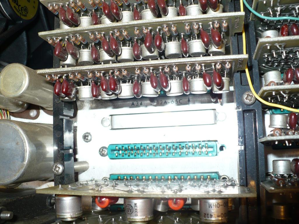


The connections to the new card (power, signals) are made on the underside of the unit; the photo below is from before the installation of the additional connector and board.

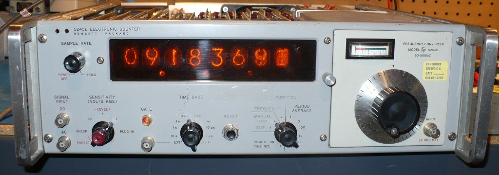
And here's the completed clock (with its top cover still off). The last two digits on the right are tenths and hundredths of a second; you can see two digits in the tenths (8 and 9) and pretty much all ten in the hundredths in this exposure.
And here's the required (shaky) video:
I think the clock will live in the band rehearsal space. Not a very complex project by the standards of modern tinkering, but one from which I learned a ton. -DRM